- Рус
- Eng
FAQ - Answer: The setup procedure of LCU-RCU (APM-150MA) communication line is given below
Answer: The setup procedure of LCU-RCU (APM-150MA) communication line is given below.
Final purpose of tuning is to is obtain link between RCU and LCU. In this case text string Link of RCU diagnostics screen will show status Norm.
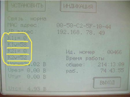
Picture 1. RCU diagnostics screen
- Parameter UTX displays the value of output voltage of input telecommand amplifier (TX)
- Parameter K1i displays number of errors while receiving of telesignalization (RX) packet from LCU. It is required to get the zero value, i.e. absence of errors.
- Parameters K1w indicates the quality factor for received signals in LCU or RCU. This parameter is not critical.
- Parameters K2i and K2w are the similar parameters that indicate the TX signal received from LCU modem.
Note 1: In APM-150MA NDB the following "master-slave" data exchange method is applied: RCU is "master" and transmits TX message to LCU, then shifts for 4 seconds to receiving mode to receive RX from LCU. If there is no RX message at RCU during this time, it transmits TX message to LCU again. If RX message reception is successful, RCU transmits TX message without 4-second-delay.
LCU is constantly receiving TX. If TX reception from RCU is successful, LCU transmits RX to RCU, then it shifts to TX receiving mode again.
Note 2: RCU and LCU have an option to disable the "master-slave" mode and force the transmitting mode by moving the jumper cup to XJ7.5. In this case the modem reference frequency tone becomes 2400 Hz. Receiving mode is actuated by moving the jumper cup to XJ7.4.
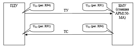
Chart of TX/RX signal level adjustment.
Way to adjust TX/RX signal level via test modes:
1. Setting the TX output signal level on RCU.
1.1. ЗJumper cups on XJ1 and XJ6 should be set to position 1-2 (see P267-330-100 Э3 "RCU link board"). In the picture, they are set to position 2-3!
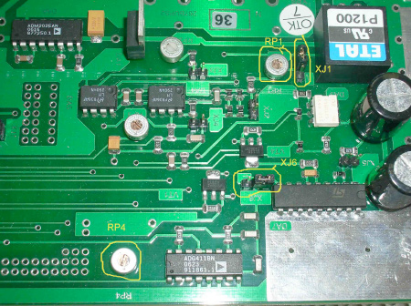
Picture 2. Explanation to jumper cup settings on the communication PCB P267-330-100
1.2. Set "only transmission" mode by moving jumper cups on XJ7.5 away. Restart RCU power supply.
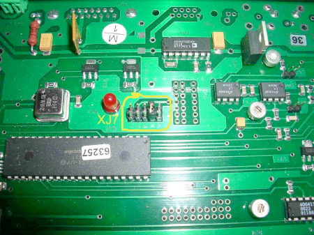
Picture 3. Example of disable "master-slave" mode and forcing the transmitting mode (XJ7.4) mode on the communication PCB P267-330-100.
1.3. Check for the TX transmission signal level on the RCU diagnostics screen. UTX should be within the limits of 8...11 V. If required, perform adjusting with use of RP4. Check point XJ5 is used for measurements.
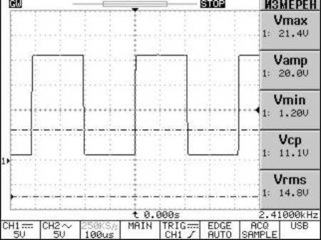
Figure 1. TX signal at check point XJ5.
2. Setting the TX output signal level on LCU.
2.1. Contactors on XJ1 and XJ6 should be set to position 1-2 (see P267-122-100 Э3 "LCU link board"). In the picture, they are set to position 2-3!
2.2. Shift LCU to test receiving mode, by setting LCU link board contactor on XJ7.4. Restart the power supply.
2.3. Check the (TX) signal level on the LCU diagnostics screen. On the LCU link board set UTX within the limits 4.0...4.5 V with help of RP1. Measure the signal after front amplifier in check point XJ4.
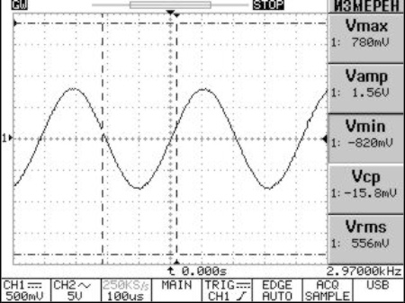
Figure 2. Check point XJ2. TX test-signal before front amplifier by dummy line of 10 km.
If tuning by RP1 is not enough for target UTX, set maximum available value on RP1 and add level with help of RP2.
3. Setting of RX output signal level on LCU.
3.1. Shift LCU to mode of test-signal transmission by setting contactor on XJ7.5 of LCU link board. Restart the power supply.
3.2. Monitor the level of (TX) transmission signal on the LCU diagnostics screen. URX parameter should be within the limits of 8...11 V. If required, perform tuning by use of RP4.
4. Setting of RX input signal level on RCU.
4.1. Shift RCU to the test-signal reception mode by setting RCU link board contactor on XJ7.4. Restart the power supply.
4.2. Check the (RX) transmission signal level on the RCU diagnostics screen. Set Urx within the limits 4.0...4.5 V with help of RP1 on RCU link board. If tuning by RP1 is not enough, set maximum available value on RP1 and add level with help of RP2.
5. Setting of the required signal levels is complete. Remove contactors from XJ7 of LCU and RCU. Restart LCU and RCU power supply.